Could somebody explain the spectrum graph? What does it mean, and why does it appear to be rotationally symmetric?
kayvonf
Everyone, this sequence of images might be very helpful for you in understanding what it means for an image to be made up as a combination of frequencies.
BryceSummers
Algorithm for Producing These Images
In the following description, the words "image" and matrix are used interchangeably.
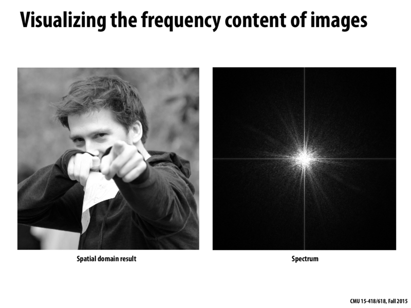
We started with an image I1, which we can think of as a matrix of floating point values representing 1 channel of color values (Grayscale Imagery).
Compute image I2 by replacing every row R in I1 with the result of a discrete Fast Fourier Transform (FFT) of R.
Compute image I3 by replacing every column C in I2 with the result of a discrete Fast Fourier transform on C.
I3 will now be an image composed of complex values with floating point coefficients.
Consider a fixed and arbitrary value v at the location (r, c) in I3. The magnitude v represents the amplitude of the sinusoidal waveform corresponding to a horizontal frequency of c pixels per cycle and a vertical frequency of r pixels per cycle. The angle of v in the complex plane relative to the direction of positive real numbers represents the phase of this waveform, which determines where the peeks and valleys are.
4.
We could stop here, because we have computed all of the frequency bins, but for aesthetic, informational, and practical filtering purposes, we perform a "fftshift", where we divide the image up into quadrants and swap each pair of mutually diagonal quadrants.
E.G: The following is a visual geometric labeling of the quadrants with (0,0) in the upper left.
12
34
We swap 1 with 4 and 2 with 3.
This puts the lower frequency signals in the middle of the image, and the higher frequency signals nearer to the extremities of the image.
We then can render the frequency space image by treating the magnitude of every value as a grayscale value, perhaps with some normalizing or scaling of the plotted colors. Please note that we can produce images for the phases of all of the values as well, but we have not shown them in this lecture, because they are quite chaotic and are not as visually informative.
To bandpass filter the image, we simply annihilate desired values in I3 to the complex value of 0 + 0i (i.e. 0).
To reconstruct the spatial domain image after the desired bands have been removed, simply follow the 1-4 in opposite order reversing the operations, i.e inverse shift the pixels, inverse discrete fourier transform the columns, inverse discrete fourier transform the rows, interpret the values as grayscale colors.
Notes:
Do you long to process colorful images? You can!! You just need decompose the image into "grayscale" images corresponding to every color channel, perform the above algorithm on each color channel, and then re-composite the image.
Could somebody explain the spectrum graph? What does it mean, and why does it appear to be rotationally symmetric?
Everyone, this sequence of images might be very helpful for you in understanding what it means for an image to be made up as a combination of frequencies.
Algorithm for Producing These Images
In the following description, the words "image" and matrix are used interchangeably.
We started with an image I1, which we can think of as a matrix of floating point values representing 1 channel of color values (Grayscale Imagery).
Compute image I2 by replacing every row R in I1 with the result of a discrete Fast Fourier Transform (FFT) of R.
Compute image I3 by replacing every column C in I2 with the result of a discrete Fast Fourier transform on C.
I3 will now be an image composed of complex values with floating point coefficients.
Consider a fixed and arbitrary value v at the location (r, c) in I3. The magnitude v represents the amplitude of the sinusoidal waveform corresponding to a horizontal frequency of c pixels per cycle and a vertical frequency of r pixels per cycle. The angle of v in the complex plane relative to the direction of positive real numbers represents the phase of this waveform, which determines where the peeks and valleys are.
4. We could stop here, because we have computed all of the frequency bins, but for aesthetic, informational, and practical filtering purposes, we perform a "fftshift", where we divide the image up into quadrants and swap each pair of mutually diagonal quadrants. E.G: The following is a visual geometric labeling of the quadrants with (0,0) in the upper left.
12
34
We swap 1 with 4 and 2 with 3.
This puts the lower frequency signals in the middle of the image, and the higher frequency signals nearer to the extremities of the image.
We then can render the frequency space image by treating the magnitude of every value as a grayscale value, perhaps with some normalizing or scaling of the plotted colors. Please note that we can produce images for the phases of all of the values as well, but we have not shown them in this lecture, because they are quite chaotic and are not as visually informative.
To bandpass filter the image, we simply annihilate desired values in I3 to the complex value of 0 + 0i (i.e. 0).
To reconstruct the spatial domain image after the desired bands have been removed, simply follow the 1-4 in opposite order reversing the operations, i.e inverse shift the pixels, inverse discrete fourier transform the columns, inverse discrete fourier transform the rows, interpret the values as grayscale colors.
Notes:
Do you long to process colorful images? You can!! You just need decompose the image into "grayscale" images corresponding to every color channel, perform the above algorithm on each color channel, and then re-composite the image.
Here are many Implementations of FFTs and inverse FFTs.
Complex Numbers!!!
462 Library implementation of Complex numbers