I'm confused as to why pacman is involved here - can't visualize how that shape is oriented around the boundary. I'm assuming that these pacman's somehow make up the boundary loop - is there another example that can help visualize this?
motoole2
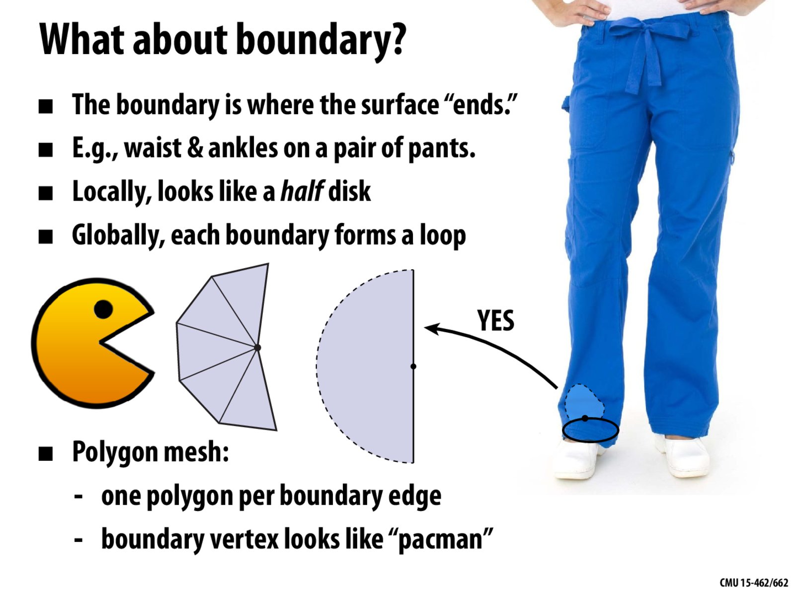
@treetrunk (I could have done a better job at explaining this today.) When a vertex is on the boundary of a mesh, the faces touching this vertex form a partial fan that looks a bit like this pacman illustration. The illustration represents the local geometry surrounding this one vertex at the boundary, and pacman's mouth represents the edge of the mesh.
This is in contrast to a vertex not on the boundary, where the faces touching the vertex form a complete fan, i.e., polygons completely surrounding the vertex (as shown in this previous slide).
The boundary loop represents a larger (global) structure associated with our mesh. Starting at one vertex along the boundary, we can write a function to trace out this loop by (1) identifying a boundary edge connected to our vertex, (2) going to the other vertex connected to this boundary edge, and (3) repeating this procedure until we return to our original vertex.
Does this help? If not, please let me know and I'll see if I can come up with some visuals to clear this up even more.
Kalecgos
Does a single boundary necessarily consist of only one face? The examples we've seen so far (and the one illustrated on the Halfedge Mesh page for Scotty3D) are consistent with this, and it seems like a potentially useful invariant, but I can imagine a single boundary which can only be formed by two or more faces, e.g. a tetrahedron with two sides missing.
motoole2
@Kalecgos First, here's a link to a slide with a discussion of how boundaries are handled in assignment 2, expanding on the comments made in class. In short, every boundary can be represented by one "virtual" face, and the face class definition includes a boolean flag to differentiate between "real" and "virtual" faces.
Now regarding this tetrahedron case, two missing faces (and the single boundary formed by these two faces) can be represented with one four-sided "virtual" polygon. This works even though the four vertices associated with this polygon do not lie on a plane. It is therefore sufficient to have one face for every boundary loop.
Although in principle one could represent a boundary with multiple faces, it is also not obvious to me that there is an advantage in doing so (perhaps someone can think of one though?).
Also, while we use "virtual" faces to represent boundaries, I will also point out that there are other ways to implement this data structure as well. For example, instead of storing a boolean flag to identify "virtual faces", one could set a halfedge's twin pointer to NULL for every halfedge on this boundary loop. This would save a bit on storage cost (no longer have to store that boolean flag), but might make the implementation of this halfedge data structure a little more complicated.
I'm confused as to why pacman is involved here - can't visualize how that shape is oriented around the boundary. I'm assuming that these pacman's somehow make up the boundary loop - is there another example that can help visualize this?
@treetrunk (I could have done a better job at explaining this today.) When a vertex is on the boundary of a mesh, the faces touching this vertex form a partial fan that looks a bit like this pacman illustration. The illustration represents the local geometry surrounding this one vertex at the boundary, and pacman's mouth represents the edge of the mesh.
This is in contrast to a vertex not on the boundary, where the faces touching the vertex form a complete fan, i.e., polygons completely surrounding the vertex (as shown in this previous slide).
The boundary loop represents a larger (global) structure associated with our mesh. Starting at one vertex along the boundary, we can write a function to trace out this loop by (1) identifying a boundary edge connected to our vertex, (2) going to the other vertex connected to this boundary edge, and (3) repeating this procedure until we return to our original vertex.
Does this help? If not, please let me know and I'll see if I can come up with some visuals to clear this up even more.
Does a single boundary necessarily consist of only one face? The examples we've seen so far (and the one illustrated on the Halfedge Mesh page for Scotty3D) are consistent with this, and it seems like a potentially useful invariant, but I can imagine a single boundary which can only be formed by two or more faces, e.g. a tetrahedron with two sides missing.
@Kalecgos First, here's a link to a slide with a discussion of how boundaries are handled in assignment 2, expanding on the comments made in class. In short, every boundary can be represented by one "virtual" face, and the face class definition includes a boolean flag to differentiate between "real" and "virtual" faces.
Now regarding this tetrahedron case, two missing faces (and the single boundary formed by these two faces) can be represented with one four-sided "virtual" polygon. This works even though the four vertices associated with this polygon do not lie on a plane. It is therefore sufficient to have one face for every boundary loop.
Although in principle one could represent a boundary with multiple faces, it is also not obvious to me that there is an advantage in doing so (perhaps someone can think of one though?).
Also, while we use "virtual" faces to represent boundaries, I will also point out that there are other ways to implement this data structure as well. For example, instead of storing a boolean flag to identify "virtual faces", one could set a halfedge's twin pointer to NULL for every halfedge on this boundary loop. This would save a bit on storage cost (no longer have to store that boolean flag), but might make the implementation of this halfedge data structure a little more complicated.