Overview
In this final assignment, you will extend some part of Scotty3D in order to make it richer, more interesting, more full-featured, and more fun. Below we have provided a large number of suggestions, with a few specific starting points. We suggest that you come up with an idea that is reasonably easy to implement starting with your existing code, rather than starting a new project from scratch (in past semesters, students who moved to a different framework or started from scratch did not do very well!). However, if you're feeling really passionate about implementing your project in a different code framework, we're glad to hear about it!
Note that we are not requiring you to hit specific technical bullet points—rather, your goal should be to build a more interesting and/or more full-featured tool that extends a previous assignment in fun and creative ways. You can achieve this goal in any way you like. In other words, we are trying to prep you for building software in the real world, where there is no pre-baked script or list of bullet points you need in order to get "points." Also note that in many of these projects you will likely have to change some of the viewer/GUI in order to expose this new functionality to the user. This type of coding can be tricky; if you are having trouble coming up with a good, simple way to modify the GUI, please consult with one of the TAs, who know the system well. Also, note that code for some functionality (e.g., Catmull-Clark subdivision) is widely available on the web. Unlike previous assignments, in this project we are encouraging you to use existing code, in order to more rapidly build up a more full-featured/interesting/fun tool. However, we will not give you credit simply for plugging in an existing source file or library! We want to see that you are building a whole that is greater than the sum of its parts. So please document and credit appropriately any use of external code or libraries when you hand in the assignment.
Truly exceptional projects may make their way back into a permanent part of Scotty3D. So aim high, and make some beautiful stuff!
Administrative Details
The official due date for your project is Friday, December 16 2016. Since this is the end of the semester, no further late days will be accepted after this final cutoff date.
A proposal for your project must be submitted by Saturday, December 3rd 2016. In particular, the proposal should:
- Be submitted to us as a web site with a publicly-accessible URL,
- Specify your name (or possibly two names, if you work with a partner)
- Give a brief description of the proposed project and what you hope to achieve—motivating images are extremely valuable here (e.g., "in a perfect world, the output of our algorithm would look like this photograph...")
- Give a list of concrete steps you will take to implement the proposed algorithm.
Your grade will be determined largely according to the goals YOU set out to accomplish! If you do not provide a well-written and well-presented writeup of your proposed project, we reserve the right to be harsh when it comes to grading. So, please take the time to put together a nice writeup.
As just one "toy" example, let's say your goal is to extend the MeshEdit code to implement creases in Catmull-Clark subdivision. You might write:
- "We will first modify the viewer to allow the user to select a sequence of edges and specify edge weights."
- "We will then modify the core Catmull-Clark routines to incorporate creases based on these edge weights."
- "Finally, we will implement a fast subdivision preview in the GUI so that edge weights can be interactively adjusted."
These bullet points should be split enough into small enough chunks that you have a concrete sense of what steps to take. Extremely high-level bullet points will make it very difficult for you to make progress, because you won't have a concrete sense of what to do next. If you're having trouble coming up with a concrete game plan, indicate which steps are giving you trouble and the staff will try to provide some guidance. Overall, a big part of this project will be developing your skill in starting with a high-level conceptual target, and turning it into concrete, actionable items that you can actually achieve. (This kind of ability is one key difference between a good developer and a stellar one!)
Finally, to allow you to implement "cooler stuff," you may work with a partner if you so desire. However, partners must be clearly indicated on your proposal statement and final project submission.
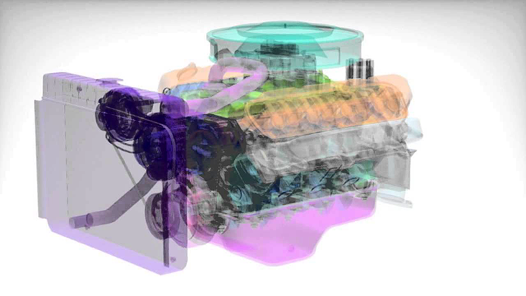
Option: Advanced Subdivision Modeler
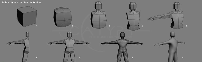
Many modern 3D modelers are based on subdivision tools that are not much different from the "MeshEdit" tool you started to build your earlier assignment. The basic idea is that the artist starts with a simple primitive like a cube, and adds more and more detail to the model via primitive operations like extruding faces and beveling edges. Here is one example video, but you can find many, many more by simply Googling "box modeling" or "subdivision modeling," which you should definitely do if you chose to pursue this project. You should also take a look at some different modeling packages, such as Wings3D, Rhino, modo, Blender, Maya, and Houdini. Many of these are commercial packages, but still offer a useful glimpse at the world of subdivision modeling. A few packages (like Blender and Wings3D) are free, and you should try downloading them and playing around with them.
Your goal will be to develop your mesh editing software into a basic subdivision modeler. Some directions of extension include:
Additional atomic editing operations. For instance, in your previous assignment you implemented edge flips, splits, and collapses. What are some convenient operations for polygon modeling? Common ones include, say, face extrusion and edge beveling. But there are many more options, and the goal of this assignment is to play around with the polygon modeling paradigm in new and creative ways.
Additional selection modes. Almost as important as convenient meshing operations are intelligent selection modes. For instance, it is very common to allow the user to select a "loop" of faces, for things like adding additional detail around the eyes and mouth (you will see this kind of operation in many videos on box modeling). Adding additional selection modes will require some re-thinking and re-tooling of the viewer itself, but all the fundamental code you need (picking, etc.) is already there.
Support for additional types of subdivision surfaces. In your assignment you implemented Loop subdivision, which is useful when working with triangle meshes. However, many natural objects are more easily modeled using quadrilateral meshes, since in general surfaces will have two orthogonal directions of principal curvature. The half edge mesh class already supports general polygon meshes; you may want to extend your subdivision support to include, say, quad meshes by implementing something like the Catmull-Clark subdivision scheme.
Fast preview of subdivided surface. Also, it's worth noticing that most professional subdivision tools allow to work on a coarse "control cage" while simultaneously getting a preview of what the final subdivided surface will look like. In other words, the user doesn't actually ever dice the surface into tiny polygons; they simply use the vertices, edges, and faces of the coarse shape as a way to manipulate the smooth subdivided surface. It would definitely be valuable in your modeler to provide this kind of functionality, either by approximating subdivision patches with simpler surfaces or simply by coming up with an intelligent scheme to update a fine subdivision mesh whenever the coarse vertices are changed. One thing to think about here is that, even after n subdivision steps, each subdivided vertex has a linear relationship to the vertices in the control cage. So, you could precompute a mapping (e.g., a matrix) from coarse positions to fine positions in order to get a fast preview (...until the connectivity of the coarse cage gets updated!).
Option: Cartoon Interpolation
In the rasterization assignment, you wrote code to draw bitmap images. If you wanted to use this software for 2D animation, you could give the user the ability to deform these images over time. The goal of this project is to enable the rasterizer to perform the type of deformation needed for cartoon animation. Here are a couple nice demos of this kind of system:
There are many ways to approach this kind of deformation, many of which can be built on top of your existing code. The simplest way would be to load up an SVG file that contains (i) an image, and (ii) a polygon sitting on top of the image that describes a rough outline or "cage." The user will manipulate the vertices of the cage, and the system will warp the image in some nice way to produce a continuous deformation of the character. By animating the polygon vertices, the character can then be animated over time using splines to interpolate the vertex positions, as in your animation system.
So, how do you deform an image according to a polygon? If your polygon were a triangle, it would be easy: just use linear inteprolation! For general polygons, there is no one simple answer—in fact, there are a large number of techniques each with different pros and cons. In some sense, all of these methods are attempting to generalize the notion of barycentric coordinates, i.e., how can an arbitrary point on the interior of the polygon be expressed as a combination of the locations of the polygon vertices? Once you know the answer to this question, deforming the image becomes straightforward. The simplest way, perhaps, is to tessellate the control polygon into many small triangles; the vertices of the fine triangulation can be updated using the cartoon interpolation scheme, and then the image can be interpolated linearly inside each small triangle (if you like, this approach is much easier to implement in OpenGL rather than the software rasterizer). However, each cartoon interpolation method will have slightly different details and requirements. Here are a few documents that provide good starting points—some of these papers are quite advanced, but should give a sense of what's possible. The first link gives a pretty good overview of current methods. The most useful parts to read are the "Introduction" and "Related Work" sections, which will give you some sense of which other methods are out there, and what might be easiest to implement for your project:
- Skinning: Real-time Shape Deformation - overview course from SIGGRAPH Asia 2014 / SGP 2015
- Generalized Barycentric Coordinates - some overview slides by Kai Hormann (image warping example near the end)
- Bounded Biharmonic Weights for Real-Time Deformation
- Smooth Shape-Aware Functions with Controlled Extrema
- Planar Shape Interpolation with Bounded Distortion
- Bounded Distortion Harmonic Mappings in the Plane
- Controllable Conformal Maps for Shape Deformation and Interpolation
Option: Advanced Dynamic Simulations
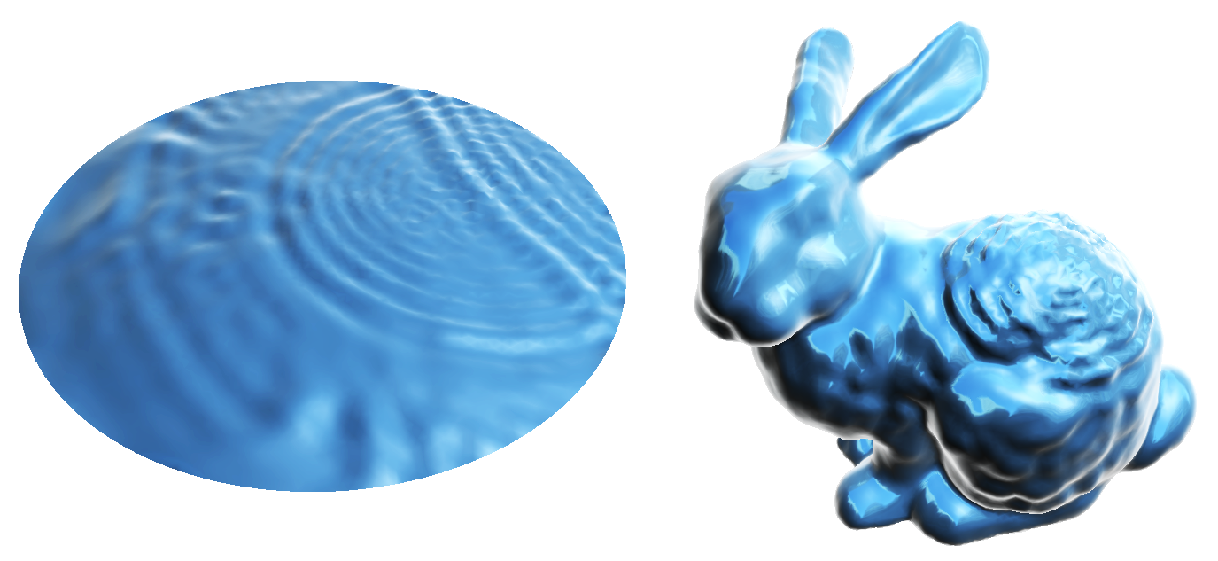
In your animation assignment, you used the basic wave equation to add interesting surface dynamics to meshes. In fact, this type of animation is highly representative of how modern physically-based animation packages simulate interesting phenomena like fluids and elastic bodies. This project would enhance your mesh-based simulation tools.
Here are several possible directions you could take toward this kind of mesh-based physical animation software:
Implement more advanced solvers. The basic schemes we introducted in class (Jacobi method, explicit time integrators, etc.) will work ok for basic simulation, but you may find that they are not particularly fast or stable. You can improve your system here by implementing a more sophisticated scheme—this shouldn't be too hard, given that the equations you're solving are all linear. For instance, integrating the heat equation using backward Euler will give you much more stable integration, leading to much larger time steps in practice. But you may notice that in order to take a backward Euler step, you have to solve a large linear system. This can be done easily using simple, freely-available linear algebra packages like Eigen (which can be added to your project by simply copying and pasting some header files into your project directory!). From there, you will need to (i) index the vertices of your mesh, (ii) build the Laplace and mass matrice according to these indices, and (iii) solve the linear system that describes the backward Euler update rule. A lot of these steps are well-documented in these course notes (see especially the section titled "Meshes and Matrices").
Implement more interesting equations. The basic model PDEs are fun to play around with, and already add a lot of additional complexity to your models, but from here there are actually a lot more interesting things you can do. Here are a few examples:
- mesh smoothing - A basic task in signal processing in general, and geometry processing in particular, is to remove noise from data by smoothing it out. One nice approach on meshes is to integrate the so-called mean curvature flow. This PDE looks a lot like the heat equation, except that rather than flowing a normal displacement (just a scalar value at each vertex), you actually flow the (x,y,z) coordinate functions themselves. Note that in order for this process to make sense, you also have to update the Laplace operator to reflect the geometry of the new surface at each step!
- spherical mapping - At the extreme, if you keep flowing a surface under mean curvature, it will eventually turn into a sphere! This paper describes a simple-but-effective modification to the above scheme that will more robustly map any surface to a sphere. These kinds of mappings are important for all sorts of applications, e.g., compressing the geometry of a surface, or comparing the anatomy of two brain scans. The authors of this method also provide some nice supplementary information.
- 3d shape editing - Many cutting-edge techniques for shape editing and manipulation are based on solving Laplace-like equations (much like the 2D animation project suggested elsewhere in this assignment). Basically the idea is that the user provides a few constraints, e.g., a few special points the user wants to move, and the system solves a Laplace-like equation for all the other vertex positions of the mesh. This kind of tool would be a very easy extension of a working Laplace equation solver; basically you would just have to provide a simple interface for selecting the pinned vertices (the GUI already allows you to click and drag on vertices). From there, there are many interesting different types of deformation to explore (harmonic, biharmonic, ...); see the link at the beginning of this paragraph for good discussion and pointers.
- bubble dynamics - This method simulates the way bubbles evolve over time. The basic flow here is actually not too hard to implement using the type of solver we've described here; most of the complexity in this paper is due to (i) optimization (making things faster), and (ii) dealing with multiple interacting bubbles. So, you could implement a simplified version that (i) skips some of the difficult optimizations, and (ii) works on only, say, one bubble, or a bubble with interesting (Dirichlet) boundary conditions.
- mesh-based surface tension - This method describes another approach to modeling surface tension, which is an essential ingredient in realistic fluid simulation.
Improved rendering. Although animation and rendering are often treated as separate topics, there is an important interplay between the two, i.e., when developing algorithms for simulation, it is prudent to think about how this data will ultimately visualized, and how different types of simulation errors and artifacts contribute to (or detract from) the fidelity of the final rendered image. For instance, if you wish to ray trace a displaced, rippling surface, then the interpolated surface normals will play a role in how well caustics show up (i.e., how smooth and artifact-free they are). Likewise, if you're really interested in efficiently rendering caustics, you may need to modify your ray tracer to use a scheme like bidirectional path tracing. Alternatively, if you want to focus more on the simulation itself but bump up the visual fidelity just a little bit, you could implement basic reflection mapping using a cube mapped environment map. (This is easily done in OpenGL on top of the existing viewer code.)
Particle Systems We have seen in the last few lectures that mass-spring systems can be used to model a large range of physical phenomena. You could, for example, model hair, cloth, or jello, tearing, fracture, plastic deformation effects, viscous flow, even fluids. Particle systems also provide a nice opportunity to experiment with different numerical integrators and time-stepping schemes. If you are feeling brave, it is not too difficult to even combine rigid bodies with mass spring systems! If you are interested in this topic, check out this great set of lecture notes on physically-based modelling.
Option: Font Rendering
In your first assignment, you wrote a rasterizer to draw 2D vector graphics. An extremely important example of 2D vector graphics is text! In other words, whenever fonts are getting rendered to the screen, some kind of 2D rasterization is needed. It's easy to dismiss text rendering as a dry, "solved" problem, but in reality typography is a beautiful and challenging subject, with a long and rich history. It also has a clear impact on the daily lives of billions of people. One possible project is to extend your rasterization engine to handle type. Possible directions include:
- Implement rasterization of cubic and quadratic Bézier curves. As we studied in one of the quizzes, these curves are needed to render either TrueType or PostScript fonts (respectively). There are two principal ways to render Bézier curves. One is to use an incremental algorithm, like the "Bresenham" algorithm we studied for lines. A more modern way is to convert explicit Bézier curves into an implicit representation, and evaluate ths implicit function at each sample in a convex region containing the curve; this approach is more amenable to parallel or GPU implementation. Finally, here's a rather old and outdated survey on font rendering that is nonetheless nicely written. (Can you give a more modern summary?) More generally, this functionality would let you render a broader class of shapes in your 2D rasterization and animation programs. Fun!
- Character layout. Given a font and a plain-text string of characters, where and how should each character display on screen? This question is deceptively simple, and has led to generations of ideas in professional typography about kerning, ligatures, and so forth. To begin with, you could implement Donald Knuth's dynamic programming line-breaking algorithm (full justification) and all the fancy special cases for font ligatures. Character width will need to be extracted from the font definition (see below).
- Implement a loader for TrueType/PostScript fonts, or link against an existing one! Obviously loading fonts is a critical part of actually rendering them, but perhaps your time is better spent on the rasterization algorithms themselves. (No reason to reinvent the wheel.)
- A completely different direction you could go is to move past traditional font definitions, and develop/design your own. For instance, what if you want animated fonts? Or fonts that encode the random variations found in handwriting? Can you come up with a nice representation for these "richer" fonts? Should you still use Bézier curves? Or, given that you already know that implicit representations lead to efficient algorithms for curve rasterization (as mentioned above), why not design a font format based on implicit representations from the ground up? How can you respect history while still moving forward? Can you add richness to font descriptions without abandoning important and hard-earned knowledge about things like kerning and ligatures? Just because there's an existing standard doesn't mean you have to adhere to it forever—your job as a thinking, breathing individual is to go out into the world and innovate.
Option: 3D Rasterization
Your first assignment focused primarily on 2D rasterization, but isn't so far from a full-blown 3D rasterization pipeline. One possible extension for your final assignment is to implement a more full-featured 3D rasterization engine, in the spirit of OpenGL. Additional features to consider might include:
- implement the camera projection matrix
- implement the viewing transform
- perform perspective-correct attribute interpolation (color, texture coordinates, etc.)
- implement depth testing by adding a Z-buffer
- implement order-independent transparency using an A-buffer
- implement simple per-pixel lighting/shading
- advanced: implement shadow mapping
- advanced: add trilinear filtering (small change from your assignment 1 implementation to get the partial right)
Overall, a fun question to think about is: what features can you implement in a software rasterizer that you cannot (easily) implement in a hardware rasterizer. Roughly speaking, modern graphics hardware is designed around a restricted set of rasterization features that were deemed to be important by the OpenGL standards board. As a consequence, it can be tricky to do things like implement an A-buffer, which is not directly supported by the hardware. But that doesn't mean OpenGL represents the "one true way" to design a rasterizer. How does rasterization change in various scenarios? Does virtual reality (VR) present new challenges for rasterization that don't show up in the traditional pipeline?
Also, what about geometric primitives other than triangles? Graphics hardware is mainly a "triangle machine," meaning that even when you draw a quad, a polygon, and even a point, it gets diced into triangles before being sent to the hardware. The reason is chip area: if you can build one little piece of hardware that renders triangles, and render everything else in terms of triangles, then you can print a much smaller silicon wafer. Software rasterizers are fun because they don't inherently have this restriction (i.e., you're not designing a chip, so you don't care about die area!). So: what other primitives can you rasterize? Interestingly enough, early NVIDIA chips supported direct rasterization of bilinear patches. There are likewise algorithms for visualizing higher-order Bézier patches or subdivision surfaces using (you guessed it) ray tracing. Much like high-performance algorithms for triangle rendering, the idea is to rasterize some region bounding (the projection of) a primitive like a Bézier patch, and then do a ray intersection with an implicit description of the patch to determine visibility, shading, etc. The (potential) advantage from a systems point of view is that you don't have to dice patches into tiny little triangles, which means you don't have to waste as much bandwidth pushing all this data through the pipeline.
Lots of directions to consider here. What's most exciting to you?
Option: Advanced Monte Carlo Rendering
Finally, you could extend the physically-based renderer you started to develop for your third assignment—as you experienced first-hand, the basic path tracing algorithm does not converge very quickly! It also doesn't capture some important (and beautiful!) physical phenomena. Here are several specific suggestions for directions you might pursue:
- Improve performance of BVH construction. For large and/or dynamic scenes, the cost of building a bounding volume hierarchy is specific. Consider, for instance, running a large, mesh-based physical simulation of water, which you then want to ray trace in order to get beautiful caustics. Lots of geometry changing in unpredictable ways—and millions of rays to properly resolve the appearance of the surface. You could improve the performance of your renderer by implementing one of the the top modern parallel BVH build algorithms such as
- Improve performance of ray tracing. There are also plenty of opportunities to improve the performance of the ray tracing itself. One possibility is to implement fast packet-based ray tracing a la the method described in, "Ray Tracing Deformable Scenes using Dynamic Bounding Volume Hierarchies".
- Implement an advanced global sampling algorithm. A very different way to reduce the cost of rendering an image is to improve the sampling strategy. In other words, since each ray can be very expensive to intersect with the scene, it makes sense to put some effort into finding paths that are likely to carry a lot of "light." The ultimate goal is to "beat the clock," i.e., your fancy strategy should not only give better estimates of the integral as a function of number of rays cast, but it should really decrease the overall render time for a fixed target level of noise (i.e., an estimate of the variance of your estimator). We discussed a number of these methods in our Advanced Rendering and Sampling lecture; a few you might consider are given in the following list (many of these methods are excellently described in the PBRT book):
- bidirectional path tracing
- Photon mapping
- Metropolis light transport—this method is quite advanced, though the "hypercube" picture we discussed in class can make it a bit easier to implement.
- Improved sampling patterns. We also discussed a variety of strategies for picking more intelligent sampling patterns (stratified sampling, low-discrepancy, blue noise, etc.). You could implement a variety of strategies and, like the previous item, compare the estimated variance of the estimator relative to the wall clock time used to render.
- Irradiance caching. A method that is extremely important in practice (i.e., almost all "real" renderers use it) but that we didn't have a chance to discuss in class is irradiance caching. In a nutshell the idea is to say: if illumination is varying slowly, you sometimes get away with interpolating existing samples rather than generating new ones. Exactly how you generate these samples (and how you interpolate them) is critical to getting good results, and plenty has been written on the subject. But even a basic irradiance caching strategy could greatly improve the utility of your renderer, in the sense that you can get far smoother images with far fewer samples.
Option: Iterated Function Systems (IFS)
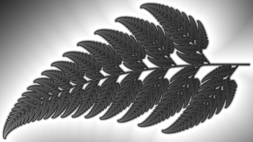
You could extend your rasterization code to render fractal images based on Iterated Function Systems. The main idea is that you start with a point and then repeatedly rasterize the point and then apply a distribution of affine transformations to it. Here are some concrete steps and features you could implement:
- Sierpinski triangle: As a warmup you should render a simple IFS such as the Sierpinski Triangle. You will need to modify the A1 code to drive the rendering via procedures instead of an SVG file.
- Barnsley Fern You can then make simple renderings of Barnsley Ferns
- Extend the SVG for representing IFS based files. You would then need to extend other relevant functions such as the file parser.
- Irradiance Caching If you were to simply plot each of the points, then you would end up with an image looking like a set of dots and would be limited in detail to the rasterization size of a point. Most images you will see on the internet never get past naive plotting. To combat this we can instead create a buffer and instead of plotting points as an opaque color, we plot their relative energies interpolated around the 4 pixels they are plotted upon. You can then compute colors for each pixel based on the irradiance cache's energy divided by the largest energy value. In other words we are mapping all energy values from 'black' to 'white'. You may need to think through you aesthetic sensibilities when deciding upon a background color and the colors on each end of the spectrum.
- Distance Function Now the question is how do we render the background in a way that is aestetically based on the IFS? One solution is to color every background pixel colors based on how far away they are from the set of points defined by the IFS. In other words the shortest distance form the background point to any point that was rasterized inside of the set. This problem is closely related to Voronoi diagrams. Here is one efficient way to go about doing this:
* Create a buffer with one value for every pixel describing how far the given location is from the IFS set. Lets call this the distance buffer. * Initialize those locations with non zero energy values in the irradiance cache to have values of 0 in the distance buffer. * Creatively propagate distance buffer values using an algorithm similar to flood fill and breadth first search. Every distance buffer location should propagate a pointer to the member of the set they are closest to into their neighboring locations that either have not been initialized yet or have distances larger than the value they would be updated to. You will need to think about which neighbors it will be most efficient to propagate values to, because you want to minimize the amount of times a given value is updated. * Color background pixels using the data in the distance buffer. This a great opportunity to experiment with color gradients and interpolation between colors. This is somewhat related to tone mapping. 6. Fractal Flame Algorithm Implement the Fractal Flame Algorithm 7. Design your own IFS! If you are tired of the same old triangles and ferns, you could and should design and formalize your own IFS. Come up with an idea for a shape, derive some affine transformations for it, implement it, render it, stylize it, make something amazing. Be sure to include the mathematics you came up with in your creative process.