
Scotty3D is a full-featured software package for 3D modeling, rendering, and animation. The only problem is that we've removed most of the features! :-)
Your job throughout the remainder of the semester is to bring Scotty3D to life by implementing core functionality. This task has been broken up into three different assignments, where you will implement the MeshEdit, PathTracer, and Animate modules. Thankfully, basic file parsing and GUI functionality (which is a total pain to write!) has already been implemented for you, so that you can focus on the core graphics tasks.
The documentation below provides some end-user information on how to use Scotty3D. Additional developer information will be provided with the assignments.
Overview
Modes and Actions
The basic paradigm in Scotty3D is that there are three different modes, each of which lets you perform certain action. For instance, in MeshEdit mode, you can perform actions associated with modeling. When in Animator mode you can perform actions associated with animation. Etc. Within a given mode, you can switch between actions by hitting the appropriate key; keyboard commands are listed below for each mode. Note that the input scheme may change depending on the mode. For instance, key commands in MeshEdit mode may result in very different actions in PathTracer mode.
The current mode and action are displayed in the upper-left corner of the screen.
Scene Buffers
Rather than a standard "undo/redo" paradigm, Scotty3D allows you to quickly load and write the scene to numbered buffers that can be quickly and easily swapped out. Therefore, rather than having a linear history of all your edits, you can store interesting intermediate results, possibly coming back to them later.
In the Scotty3D interface there are 10 buffers, associated with the keys 0 through 9. To write the current scene to a buffer, you simply press the w key, followed by the buffer number you want to write to. For instance, w and then 3 will write to buffer number three. Likewise, to load a scene from a buffer, you press l (i.e., lowercase L) and then a number. Note that loading a buffer will overwrite the current scene! If you want to preserve the current scene for later use, you should write it into an unused buffer before loading an earlier buffer. Likewise, writing into a previously-used buffer will overwrite the contents of that buffer. Finally, loading from an unused buffer will have no effect (the scene will remain unchanged).
Another nice feature of the buffer system in Scotty3D is that it is persistent across different sessions, i.e., if you quit Scotty3D (or it crashes...) you can still load your stored scenes from the buffers when you restart the program. (These buffered scenes are stored as COLLADA files named Scotty3D_bufferN.dae in the same directory from which you execute Scotty3D, which means you can also copy them or open them in other applications.)
MeshEdit
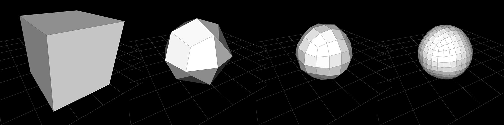
When in MeshEdit mode, Scotty3D provides a polygon-based 3D modeler with basic subdivision capabilities. The central modeling paradigm is "box modeling", i.e., starting with a simple cube, you can add progressively more detail to produce interesting 3D shapes. You can also use subdivision to get smooth approximations of these shapes.
MeshEdit supports three actions (NAVIGATE, EDIT, and BEVEL), plus a collection of mesh editing commands that are available from any mode.
Note that MeshEdit (and more broadly, Scotty3D) will only operate on meshes that are manifold (i.e., the union of faces containing any given vertex v is a topological disk). Likewise, all mesh operations in Scotty3D will preserve the manifold property, i.e., manifold input will always get mapped to manifold output. This property is key for ensuring that many algorithms in Scotty3D are "well-behaved", and that it always produces nice output for other programs to use.
NAVIGATE
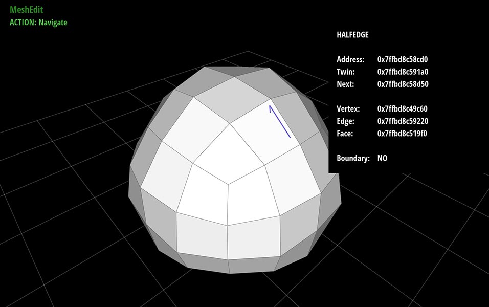
In this mode you can move the camera around, and inspect mesh elements by left-clicking on vertices, edges, faces, and halfedges. Information about these elements (including debugging information) will be shown in the info panel in the upper-right region of the screen. The camera can be manipulated in three ways:
- Rotate - left-clicking on the background (i.e., not on any scene object) and dragging will rotate the scene.
- Zoom - using the scroll wheel, or scrolling on your trackpad, will zoom the scene in and out.
- Translate - right-clicking on the background (or using multi-touch on a trackpad, e.g., two-finger click-and-drag) will translate the camera around the scene.
EDIT
In this mode you can change the geometry (i.e., the shape) of a mesh by clicking and dragging on mesh elements (vertices, edges, faces, and halfedges). Clicking and dragging will translate an element in directions parallel to the view plane. Clicking on an element will also invoke a transformation widget, which allows elements to be manipulated with a respect to a particular coordinate axis. Note that the transformation widget has three modes of operation, which you can toggle through either by (i) repeatedly pressing the e key, or (ii) holding down a modifier key:
* Translate (control) - move the selected element along X, Y, and Z axes. Clicking the handle in the center will perform a free-translate (parallel to the screen).
* Rotate (alt/option) - rotate the selected element around X, Y, and Z axes.
* Scale (shift) - perform a nonuniform scale along X, Y, and Z axes. Clicking the handle in the center will scale the element uniformly.
Note that on some platforms, the modifier keys may not be interpreted properly---in this case, you can still access the three tranformation modes by repeatedly pressing the e key.
![]()
BEVEL
The bevel action creates a new copy of the selected element that is inset and offset from the original element. Clicking and dragging on an element will perform a bevel; the horizontal motion of the cursor controls the amount by which the new element shrinks or expands relative to the original element, and the vertical motion of the cursor controls the amount by which the new element is offset (in the normal direction) from the original element. It is important to note that a new element will be created upon click even if no inset or offset is applied. Therefore, if you're not careful you may end up with duplicate elements that are not immediately visible. (To check, you can drag one of the vertices in Edit mode.)
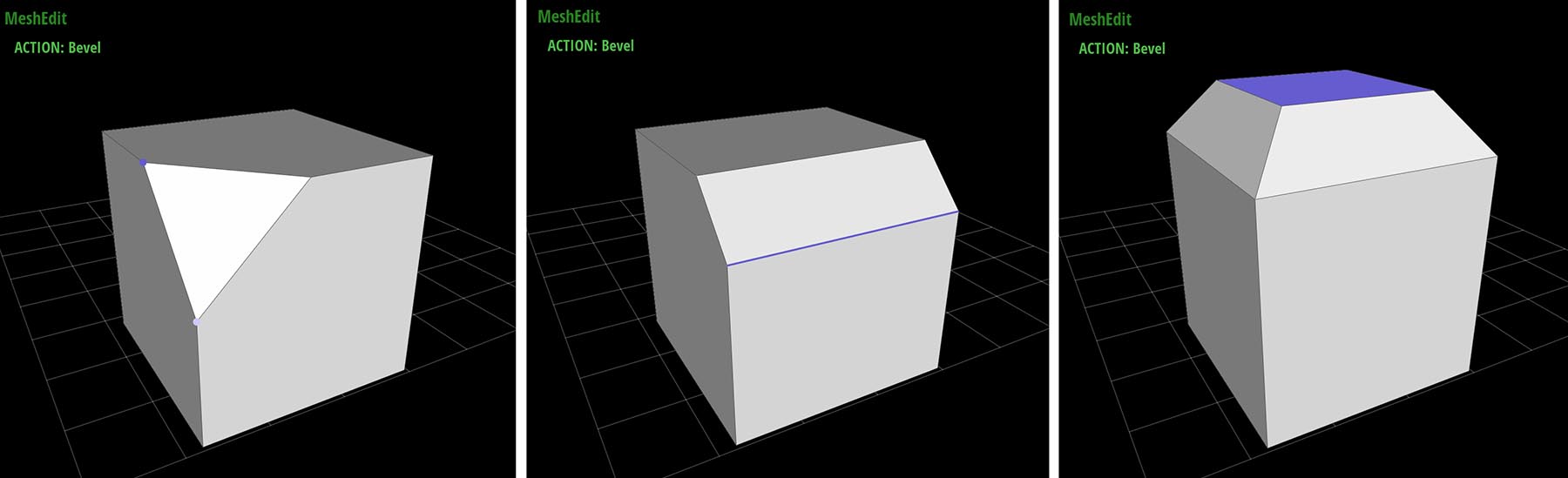
There are three possible types of bevels:
VertexBevel - The selected vertex v is replaced by a face f whose vertices are connected to the edges originally incident on v. The new face is inset (i.e., shunken or expanded) by a user-controllable amount, and also offset by a user-controllable amount in the normal direction (not shown here).

EdgeBevel - The selected edge e is replaced by a face f whose vertices are connected to the edges originally incident on the endpoints of e. The new face is inset and offset by some user-controllable amount, as with the vertex bevel.

FaceBevel - The selected face f is replaced by a new face g, as well as a ring of faces around g, such that the vertices of g connect to the original vertices of f. The new face is inset and offset by some user-controllable amount.

CONNECTIVITY EDITING
In addition to beveling, a variety of commands can be used to alter the connectivity of the mesh (for instance, splitting or collapsing edges). These commands are applied by selecting a mesh element (in any mode) and pressing the appropriate key, as listed below. Local mesh editing operations include:
EraseVertex - The selected vertex v together with all incident edges and faces will be replaced with a single face f, that is the union of all faces originally incident on v.

EraseEdge - The selected edge e will be replaced with the union of the faces containing it, producing a new face e (if e is a boundary edge, nothing happens).

EdgeCollapse - The selected edge e is replaced by a single vertex v. This vertex is connected by edges to all vertices previously connected to either endpoint of e. Moreover, if either of the polygons containing e was a triangle, it will be replaced by an edge (rather than a degenerate polygon with only two edges).

FaceCollapse - The selected face f is replaced by a single vertex v. All edges previously connected to vertices of f are now connected directly to v.

EdgeFlip - The selected edge e is "rotated" around the face, in the sense that each endpoint moves to the next vertex (in counter-clockwise order) along the boundary of the two polygons containing e.

EdgeSplit - [Note: this method is for triangle meshes only!] The selected edge e is split at its midpoint, and the new vertex v is connected to the two opposite vertices (or one in the case of a surface with boundary).

GLOBAL MESH PROCESSING
A number of commands can be used to create a more global change in the mesh (e.g., subdivision or simplification). These commands can be applied by selecting any element in the target mesh (in any mode) and pressing the appropriate key. Note that in scenes with multiple meshes (e.g., those used by the PathTracer), this command will be applied only to the selected mesh.
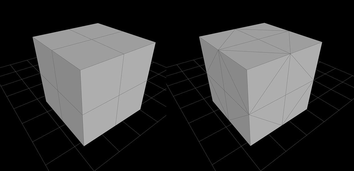
- Triangulate - Each polygon is split into triangles.
- Linear subdivision - Each polygon in the selected mesh is split into quadrilaterals by inserting a vertex at the midpoint and connecting it to the midpoint of all edges. New vertices are placed at the average of old vertices so that, e.g., flat faces stay flat, and old vertices remain where they were.
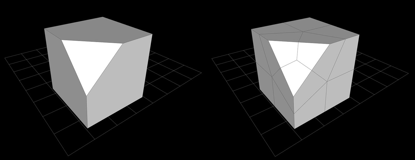
- Catmull-Clark subdivision - Just as with linear subdivision, each polygon is split into quadrilaterals, but this time the vertex positions are updated according to the Catmull-Clark subdivision rules, ultimately generating a nice rounded surface.
- Loop subdivision - [Note: this method is for triangle meshes only!] Each triangle is split into four by connecting the edge midpoints. Vertex positions are updated according to the Loop subdivision rules.
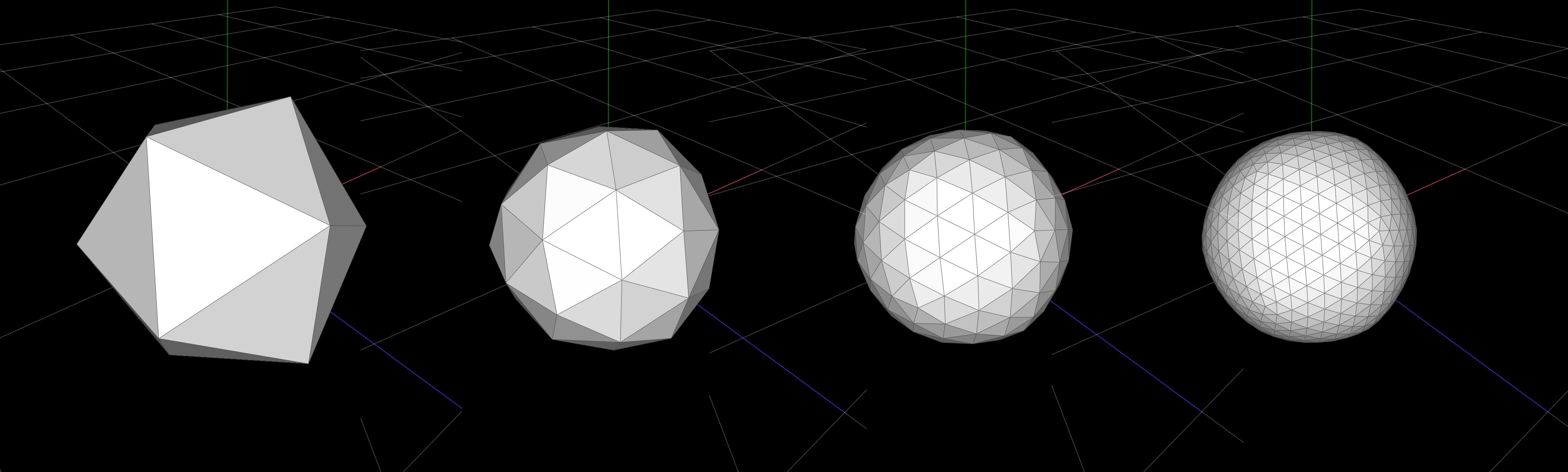
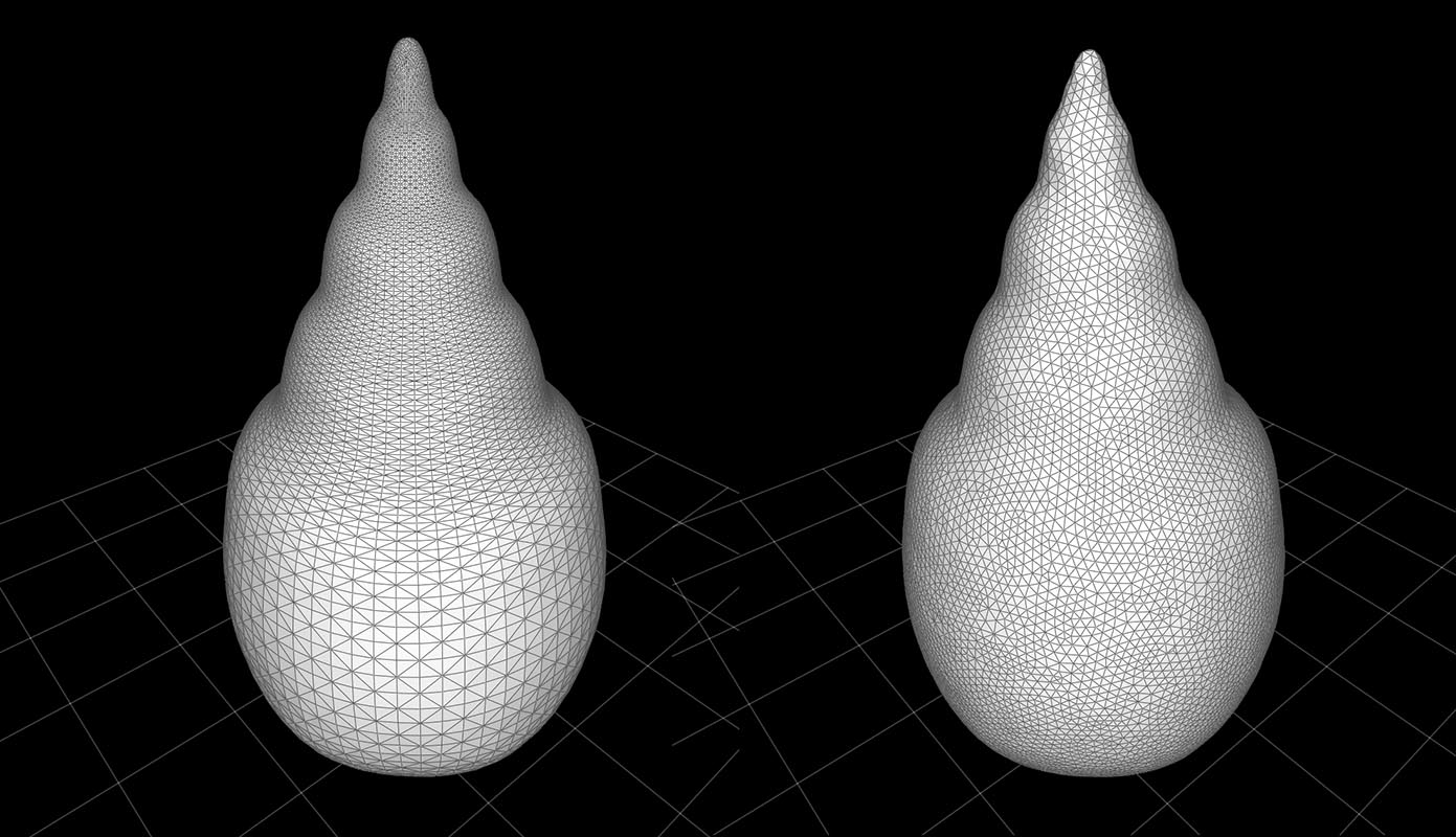
- Isotropic Remeshing - [Note: this method is for triangle meshes only!] The mesh is resampled so that triangles all have roughly the same size and shape, and vertex valence is close to regular (i.e., about six edges incident on every vertex).
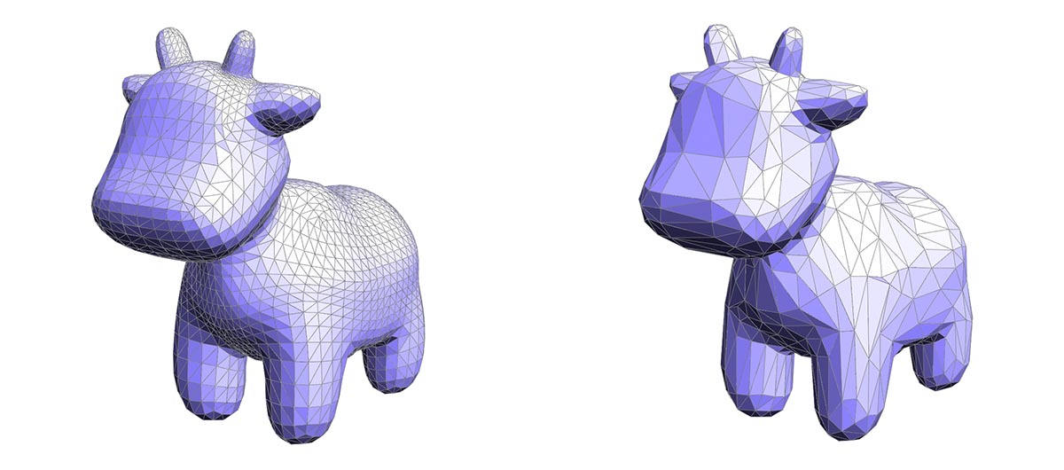
- Simplification - [Note: this method is for triangle meshes only!] The number of triangles in the mesh is reduced by a factor of about four, aiming to preserve the appearance of the original mesh as closely as possible.
KEY COMMANDS
| Key | Action |
|---|---|
space |
switch to navigate mode |
tab |
show/hide info panel |
hold control |
temporarily switch to translation in edit mode |
hold shift |
temporarily switch to scaling in edit mode |
hold alt/option |
temporarily switch to rotation in edit mode |
e |
cycle through (e)dit modes |
b |
toggle bevel mode |
n |
select next halfedge |
t |
select twin halfedge |
h |
select halfedge of current element |
T |
Triangulate mesh |
s |
subdivide Catmull-Clark |
S |
Subdivide linear |
backspace/delete |
erase selected edge |
f |
flip selected edge |
c |
collapse selected edge |
p |
split selected edge triangle meshes only! |
u |
upsample triangle meshes only! |
i |
isotropic remesh triangle meshes only! |
d |
downsample triangle meshes only! |
w then 0--9 |
write scene to numbered buffer |
l then 0--9 |
load scene from numbered buffer** |
PathTracer
For assignment 3, you will implement Scotty3D's path tracer that can render pictures with global illumination effects. The first part of the assignment will focus on providing an efficient implementation of ray-scene geometry queries. In the second half of the assignment you will add the ability to simulate how light bounces around the scene, which will allow your renderer to synthesize much higher-quality images.
Rendered Output Mode and BVH Visualization Mode
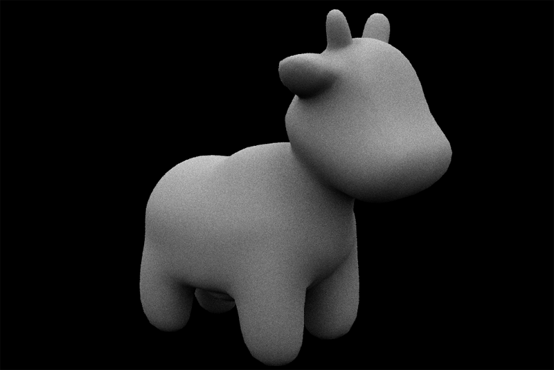
In addition to the mesh edit mode, the app features two other modes. Pressing the R key toggles display to the rendered output of your ray tracer. If you press R in the starter code, you will see a black screen (You have not implemented your ray tracer yet! ). However, a correct implementation of the assignment will make pictures of the cow that looks like the one below.
Pressing E returns to the mesh edit mode. Pressing V displays the BVH visualizer mode, which will be a helpful visualization tool for debugging the bounding volume hierarchy you will need to implement for this assignment.
Importantly, both R and V mode depends on correct implementation of triangulation, especially when rendering generic polygon meshes. Without triangulation, generic polygon meshes will not be correctly in both these modes.
KEY COMMANDS
| Command | Key |
|---|---|
| Return to mesh edit mode | M |
| Show BVH visualizer mode | V |
| Show ray traced output | R |
| Decrease area light samples (RT mode) | - |
| Increase area light samples (RT mode) | + |
| Decrease samples (camera rays) per pixel | [ |
| Increase samples (camera rays) per pixel | ] |
| Descend to left child (BVH viz mode) | < |
| Descend to right child (BVH viz mode) | > |
| Move to parent node (BVH viz mode) | ? |
| Reset camera to default position | SPACE |
| Edit a vertex position | (left-click and drag on vertex) |
| Rotate camera | (left-click and drag on background) |
| Zoom camera | (mouse wheel) |
| Dolly (translate) camera | (right-click and drag on background) |
The following are pathtracer app command line options, which are provided for convenience and to debug debugging:
Commandline Options
To run the application, other than this command
./scotty3d ../cube.dae
we provide the following commandline options for convenience and debugging purposes.
| Commandline Option | Description |
|---|---|
-t <INT> |
Number of threads used for rendering (default=1) |
-s <INT> |
Set the number of camera rays per pixel (default=1) (should be a power of two) |
-l <INT> |
Number of samples to integrate light from area light sources (default=1, higher numbers decrease noise but increase rendering time) |
-m <INT> |
Maximum ray "depth" (the number of bounces on a ray path before the path is terminated) |
-h |
Print command line help |
Animator
You can enter the animator mode by pressing 'a' or 'A' in any of the other modes. If you wish to edit the underlying skeleton of the mesh, you can toggle the ghosted (semi-transparent) mode by pressing 'g' or 'G'.
Rigging Action
You can enter the create joint action by pressing 'c' or 'C' after you enter animator mode. You can create new joints by first selecting a parent joint, then clicking anywhere else on the screen. From thereon, you can keep clicking on the screen to create a chain of joints. If you want to branch off at a joint, simply click on the joint to branch off of, then start another chain from there.
You can exit create joint action by pressing 'c'/'C' again or pressing any other key that takes you into a different action.
Editing Skinning Weight Threshold Radius
Each joint has a radius associated with it which controls which part of the mesh it affects when it is animated. The radius is visualized by the blue capsule around each joint segment. You can press 'd' or 'D' to trigger the action which allows you to edit the radius of this capsule. After you enter Change Threshold Radius action, you can click on a joint and drag the mouse up or down while left clicking to change its threshold radius.
Posing Action
After laying out the skeleton and adjusting the skinning weight radius, you can start posing the character in the posing action. You can enter this action by pressing 'p' or 'P'. In posing action, you may select any joint and use the rotation widgets to change the joint angles.
Toggling Linear Blend Skinning with Threshold
You can press 'u' or 'U' to toggle between linear blend skinning with or without threshold.
Inverse Kinematics
Multiple targets can be specified for IK purposes. To specify an additional target, just select a new joint and right click. To clear all targets, press 'i' or 'I'.
Animation Keyframe
A new keyframe is created whenever you edit any of the objects in the scene. You should first select the appropriate time on the timeline below, before you make any changes to the objects in the scene. If you want to animate the characters, you should do that by animating the joints you created using the rigging action above. The joints are meant to be rotated only. You may cycle through different modes of editing by pressing the 'e' or TAB key.
Saving the Skeleton and Animation
The read and write to buffer functions have been upgraded to also read and write the skeleton and animation information. Switch to mesh edit mode first, then press 'l' for load or 'w' for write and numbers from (0-9) to read or write your work.
Physical Simulation
Whenever the timeline is playing, a simulation of solving the wave equation: $$f^{''} = \Delta f$$ on all meshes in the scene, where values of $f$ are shown as offsets in the normal direction. Without any specified initial conditions, this wont change the mesh at all, but when conditions are specified this will give the appearance of waves propagating along the surface of the mesh. An offset is specified by using the wave action, triggered by pressing 'w' or 'W', which will allow you to move vertices in the normal direction, to give them an initial offset, and to give a more natural looking result, will give a Gaussian smoothed offset to a neighborhood of the vertex. There is no way to keyframe waves or save state about the waves. To completely reset the offsets of the mesh, press 'z' or 'Z'. The wave simulation preserves the average offset across all vertices, so when a vertex is dragged up, others will move slightly down, and vice versa, in order to preserve this at 0.
There are 2 different integrators that can be used to simulate waves, Forward Euler and Symplectic Euler, and Forward Euler is chosen by default. Forward Euler is a less stable integration approximation, so waves simulated with it may 'blow up' and produce unnatural results!
Additionally, different timesteps can be supplied, by using the '+' and '-' keys. Note that larger timesteps will usually lead to less stable results! Different damping factors can also be supplied by using SHIFT + '+' or '-'. A damping factor of 0.0 means there is no damping, and a value of 1.0 won't propagate any waves, it'll just smooth the mesh out until its back to its original shape.
KEY COMMANDS
| Command | Key |
|---|---|
| Enter animate mode | A |
| Enter create joint action | C |
| Enter capsule radius edit action | D |
| Toggle ghosted mode (semi-transparent) | G |
| Enter Inverse Kinematics action | I |
| Return to mesh edit mode | M |
| Enter object edit action | O |
| Enter posing action | P |
| Toggle linear blend skinning with threshold | U |
| Enter wave action | W |
| Reset all wave offsets | Z |
| Raytrace Animation (From beginning) | N |
| Rasterize Animation (From beginning) | T |
| Cycle through different edit widgets in object edit action | E or Tab |
| Increase / Decrease Timestep for Physical Simulation | PLUS/MINUS |
| Increase / Decrease Damping Factor for Physical Simulation | SHIFT + PLUS/MINUS |
| Change Simulation to use Forward Euler | F |
| Change Simulation to use Symplectic Euler | S |
| Edit a vertex position | (left-click and drag on vertex) |
| Rotate camera | (left-click and drag on background) |
| Zoom camera | (mouse wheel) |
| Dolly (translate) camera | (right-click and drag on background) |
| Reach for Point under Cursor with IK | (right-click and hold in IK mode) |
TIMELINE CONTROLS
| Command | Key |
|---|---|
| Play / Pause | Space |
| Move Forward / Backwards | Right/Left |
| Step Forward / Backwards (One Frame) | ALT + Right/Left |
| Jump to Beginning / End | CTRL + Right/Left |
| Move to Next/Previous Keyframe | SHIFT + Right/Left |
| Increase / Decrease Timeline Length (1 second) | Up/Down |
| Toggle Looping | L |
| Make this frame a keyframe for Selected Object | K |
| Make thie frame a keyframe for All Objects | SHIFT + K |
| Delete Keyframe for Selected Object | Delete/Backspace |
| Delete Keyframe for All Objects | SHIFT + Delete/Backspace |